All posts by Grant

A low cost, easy to build diy valve/tube tester

***My valve tester prototype is up for sale for A$300 plus postage. Only available to Australia. To purchase, contact me at my email address. First in, best dressed!!***

For quite some time I have been looking at developing a design for a diy valve/tube tester that is easy to build and uses readily available, low cost parts. A valve tester is an invaluable tool for those who wish to build and repair valve amplifiers.

Old vintage valve testers are available online, but most of them provide only a crude “go/no-go” result. They also fetch ridiculous prices for such simple tests. What is really needed is a tester that will measure a valve at true operating conditions.

In looking at a new valve tester design, I wanted it to provide these features:

1. Provide emission readings at the recommended databook operating conditions (Plate, Screen and Grid voltages)
2. Provide Gm or mutual conductance readings, directly or indirectly
3. Test valves for internal shorts
4. Test for “gassy” valves – valves whose internal vacuum has been compromised
5. Test a wide range of valves, from 12AX7s to KT88s and any other “receiving” class of valve
6. Be expandable with options to include heater/cathode leakage testing, other valve bases, different heater voltages, “life test” etc

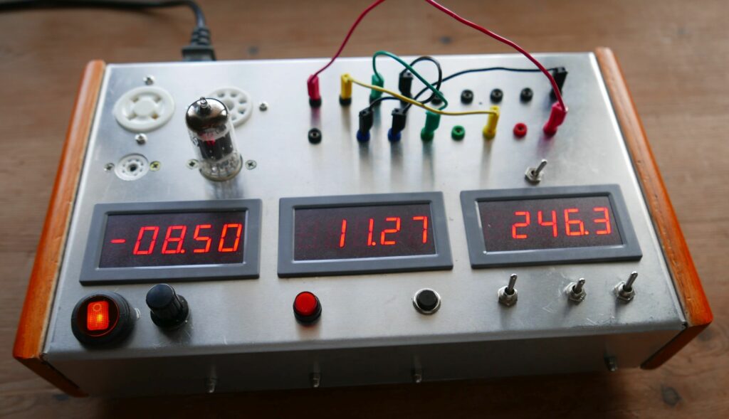
I have recently completed the following tester design which does a great job of testing any valve/tube in the “receiving” class. Unlike the old “emission” testers of the past, this low cost tester provides a true test of a valve at valve databook conditions. In addition, it tests for shorts and “gassy” valves with the ability to measure the Gm or transconductance of a valve. It uses low cost, readily available parts and can be built for well under A$100.

Full design and constructional details can be downloaded by clicking on this link:

An inexpensive, easy to build diy valve tester

Here is the completed unit testing a KT88 valve:

OLYMPUS DIGITAL CAMERA

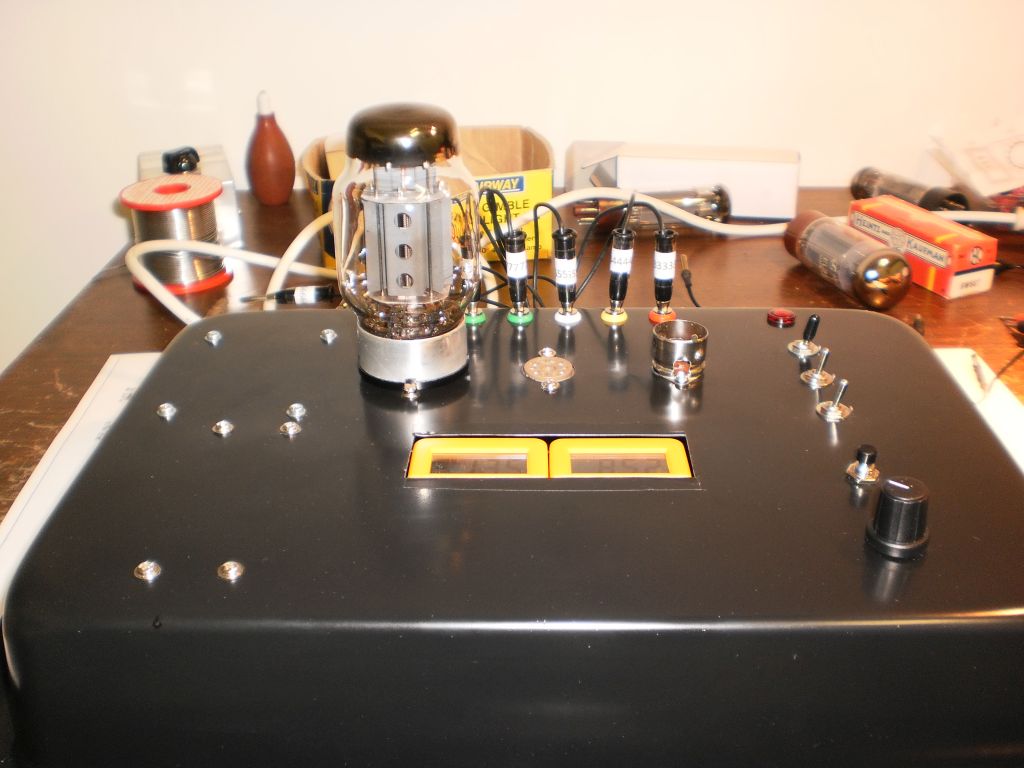
8/5/2019 Some photos of another finished tester from Rob in the UK

And another successful build from Johan:

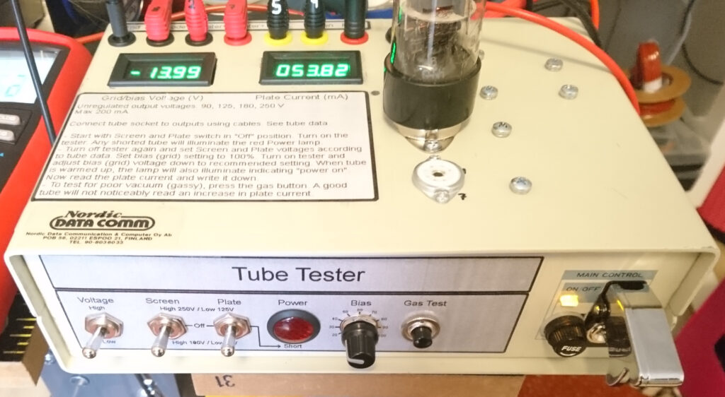
And another build by Chang

And another build by Robin from the Netherlands
The internals of Robin’s tester
And another recent build by Lars!

Safety considerations for valve amp building

There is often considerable concern out there about the safety aspects of building valve amps, and with good reason. Even the simplest valve amp designs like my Lamington Junior generate a high voltage supply of  over 250V DC to operate the valves, and accidental contact with this voltage will be unpleasant at best, and potentially more dangerous.

However, building valve amplifiers need not be dangerous if you are informed about the risks, and take the necessary precautions to ensure the safe construction, testing and operation of valve amplifiers. Being aware of a few simple strategies can make amp building safe for you and for those around you.

Here are some practical strategies that you can employ to ensure a safe environment for building and using your own valve amp:

1. The use of an ELB (earth leakage breaker) in the work environment is highly recommended. ELBs work to protect you if there is an accidental contact with the 240V mains. Most houses and workplaces have them installed – make sure you have one fitted.

2. Don’t work on your amplifier in a damp environment and make sure you are wearing shoes with insulated soles and preferably a floor that is insulated e.g. carpet or wood.

3. Make sure that ALL 240V mains wiring in your amp is properly insulated. I always use heatshrink tubing to insulate the primary leads of power transformers, fuse holders and mains switches. A good check is to follow all of the connections in your amp from mains active to mains neutral and make sure that every connection is covered with heatshrink or otherwise insulated.

4. Make sure that your amp is properly earthed by checking for zero resistance between the earth pin of the mains plug and your amp chassis with a multimeter.

5. Make sure that ANY wiring on the top of the chassis that is in contact with high voltage (transformer lugs, top caps of output valves if you are using them) is properly insulated.

6. Use the colour of wiring underneath the amp to indicate the presence of high voltage. The convention is to use red for HT supplies, and other “hot” colours like orange and yellow for other connections that have high voltage present. This assists you to keep away from these points when checking a working amplifier.

7. Don’t work on an amplifier when you are tired or distracted – you need to have all of your attention focussed on the job at hand and to avoid potential danger. Ideally, don’t work on your amplifier alone – have someone nearby to assist you if needed.

8. Before working on or making changes to an amp, disconnect the mains lead from the amp and wait for the high voltage capacitors in your amp to discharge. You can then safely work on your amp.

9. If you need to check voltages in your amp with a multimeter, with your amp turned off first clip the black (negative) multimeter lead to an appropriate earth point on the amp chassis. Then turn your amp on, and with one hand safely away from the amplifier use your other hand to hold the red multimeter probe and check the appropriate voltage point. This ensures that even if you were to accidentally touch a point in the circuit at high voltage, no current can flow through your body causing electric shock.

A new 2W low power amp design

I have just finished prototyping a new 2W Valve Heaven amp design called the “Lamington Junior”. I’m pretty pleased with it, as the design has been a long time in development. The design brief was for a low power amp that delivered a significant amount of clean, “chimey” headroom and also a great overdrive tone which is what it delivers! What is especially cool is that it runs from a 12V AC plugpack, so a newcomer to amp building can do so with no contact at all with the 240V mains making it a safer amp to build.

I am currently building a second prototype which will be easier to construct. I’ll soon have the design details including schematics available here at valveheaven.com. Soon to come will be construction manuals and kits for prospective builders.

Watch this space 😉

***UPDATE*** 13/1/2015  

Well, as promised, I have now posted the full design details and schematic diagram for the Lamington Junior here. I am very pleased with this amp, and it has now become a favourite here to play through at home, and I feel sure it will become as successful as its big brother, the Lamington 🙂

I will be making full kits and a construction manual for this amplifier available early Feb 2015 for $195 plus post for the DIY kit and $49 plus post for the DIY manual. Kits and the construction manual are now available.

***UPDATE*** 16/2/15

Several Lamington Junior kits have now been purchased with the builders very happy with their new amp. I just received this email from a customer who had never constructed an electronic project before:

Hi Grant,  I finally got it working (1k8 was in the wrong spot), all good. Thanks for your help, I will play with this one for a while and then i will try the Lamington 15w. Since I have no previous electronic experience I found the whole kit very easy to follow as a beginner. Thanks again!

Some feedback from a recent Lamington builder

I continue to receive very favourable feedback from builders of Lamington amps as to how happy they are with how the amp sounds. To some degree, this is a little surprising, as the Lamington amp was developed to be a low cost introduction to valve guitar amp building and not necessarily to be a tone monster. That it sounds so good is a real bonus, and makes it doubly worth building.

This email is typical of responses I receive:

Hi Grant,

Just wanted to let you know that we fired up the lamington last night, and….

 …it was amazing!

 I was truly taken with how great it sounded. We ran it through my 4×12 with celestion vintage 30’s and it was really great. The tone is excellent and I was loving how responsive to touch it was. It seemed nice and clean with gentle playing, and then you dig in a bit and it rips your head off… Seems at first play like it has great cleans (with the right amount of chime) and great bluesy overdrive. 

I think you are really onto something with the lamington, which of course you knew! (I’m not sure I did!)

 Any plans for other amps…? (Yes, the Lamington III design is now released)

Thanks again for all your help with this – it’s truly one of the best amps I think I’ve played.

Kind regards,

Samuel


Tips for keeping your amp in top condition

I came across these tips for maintaining your amp some time ago – some good advice for keeping your amp in top condition!

1. Always make sure the speaker is plugged in properly before turning on your amplifier. Failure to do so may cause damage to your output transformer or output valves.

2. Make sure your amp is properly grounded check the mains power cord to make sure it is not damaged.

3. Have your power output valves (6V6, 6L6, 6BQ5, 6550, 6CA7, EL34, EL84 etc.)  changed or checked if you notice a dullness in your sound. If you see glowing red plates in your output valves, STOP! You either have faulty valves or circuit trouble, and failure to turn the amp off usually results in major blown parts ($$$). The preamplifier valves, 12AX7 and 12AT7 etc should last for several changes of output valves. If you hear jingles, rattles, pops, squeals or if the gain or attack decreases, it may be time to have these valves changed or checked.

4. Transport your amp on a padded surface. Amps transported on the bare metal floor of a van or unpadded boot of a car may have the elements in the valves shaken loose and cause microphonic rattles or worse, short when next powered up at a gig. Treat your amp gently and it will last longer!

5. Follow the amplifier manufacturer’s recommendations about fuse changing. Never, ever use a fuse of a higher rating than called for, or you may wind up with a ($$$) blown power or output transformer.

6. If your amp has an impedance selector, such as Marshall, HiWatt, some Ampegs, etc., place the amp in standby before changing the impedance. Also, be sure to select the correct impedance for the type and number of speakers being used.

7. Use a thick wired cable for speaker hookup. Don’t use thin coaxial guitar cables as speaker wire if possible. This is especially true for bass, where damping factor, tone and watts could be easily lost.

8. If you hear your amp cutting in and out, reduce the amp volume then wiggle the speaker cord. If this influences the cutting in and out, STOP! An intermittently open or shorted speaker connection or cord might damage your amplifier.

9. Keep all cable ends clean. Dirty input jacks cause intermittent crackles and hums sometimes attributed to more serious problems.

10. After powering up your valve amp, look at the output valves (the bigger valves). If the valves’ plates are glowing red hot, STOP! This symptom takes moments to show up and just a few more moments to destroy the output transformer or other parts. The problem could be as simple as faulty valves, or you could have other trouble, such as bias supply failure. A new set of output valves plugged into a seriously malfunctioning amplifier can be ruined in a very, very short time. When in doubt, have your amp tested by a competent technician.

11. Give your amp plenty of ventilation. A fan blowing on the output section of the amp will keep things cooler and generally increase the service life of the electronic components in the amp greatly. An easy way of accomplishing the cooling process is to purchase a small table fan at a discount store (around $20) and place the fan behind the amp blowing into it. The cooler your amp runs, the longer it will run. Your capacitors will especially love you if you keep them cool. Never place the amp with its back against a wall. This will severely limit the natural ventilation the manufacturer has hopefully built in.

12. Do not move your amplifier immediately after shutting it off. Let the amp cool down for a few minutes before moving or transporting it.


A very cool amp design tool

For those who have not yet seen it, Duncan Munro has available a very cool amp design tool at his website:

http://www.duncanamps.com/tsc/

The freeware Tone stack calculator program allows you to play with a range of virtual tone stack circuits – you can see several tone stack circuits from Fender, Marshall, Baxandall etc and adjust each “virtual” component to see how it changes the response of the tone stack.

Here is what it looks like:

TSC

I encourage anyone to download it and “plug in” your favourite tone stack and see visually how each component shapes the sound. I use TSC on a regular basis to check different tone stacks I am planning for different amp designs – recommended!